Water Processing Plant
Uploaded at:
2026-09-24
Size and Formats:
1280x800
SVG, PNG, JPG, WebP
Description  :
:
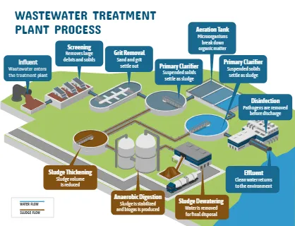
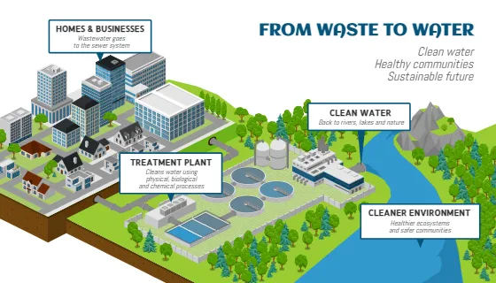
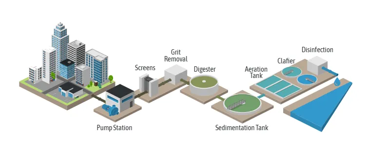
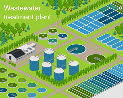
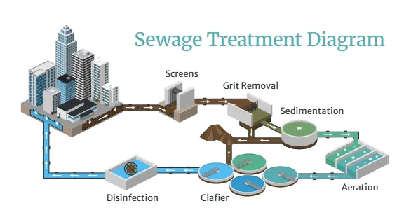
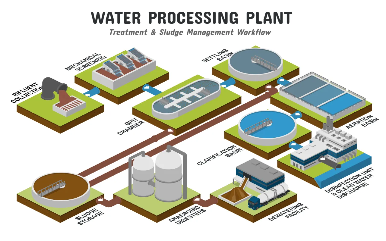
This isometric diagram shows a wastewater treatment plant with two parallel flows: a water path (blue pipes) and a sludge path (brown pipes). Raw wastewater enters through the influent collection pipe and grated inlet, then passes through mechanical screening, where rags, plastics, and other large debris are removed. Next, the grit chamber lets sand, gravel, and other heavy inorganic particles settle out, and the settling basin lets suspended solids sink as sludge. In the aeration basin, air is added so microorganisms can break down dissolved organic matter, and the clarification basin then lets that microbial mass settle, leaving clearer water. Finally, the disinfection unit kills pathogens before the clean water is discharged to the waterway on the right. Meanwhile, the brown pipes carry settled solids from the treatment stages to sludge storage, and from there to the anaerobic digesters, where bacteria break the sludge down without oxygen, reducing its volume and typically producing biogas. The last step is the dewatering facility, which squeezes out the remaining water and loads the resulting solids onto a truck for disposal or reuse.